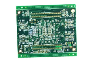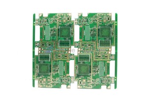
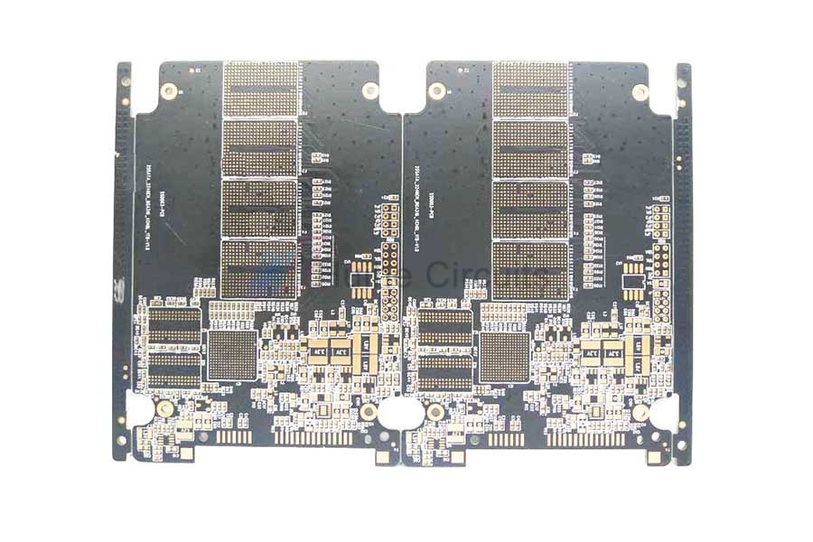
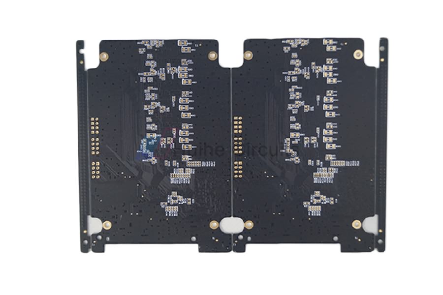
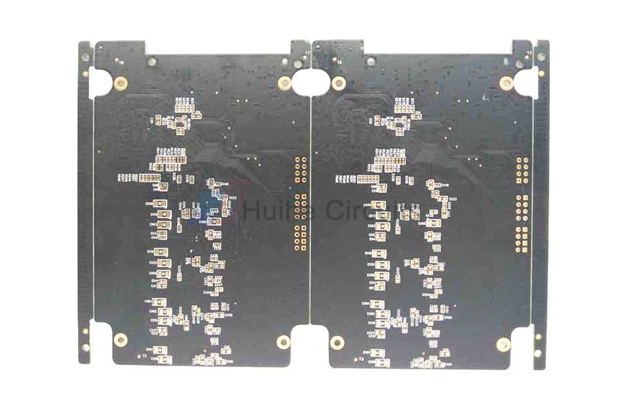
6 Layer FR4 ENIG Via In Pad PCB

Impedance Characteristics Of PCB
According to the signal transmission theory, the signal is a function of time and distance variables, so every part of the signal on the line may change. Therefore, the AC impedance of the transmission line, that is, the ratio of voltage change to current change, is determined as the characteristic impedance of the transmission line.
The characteristic impedance of the transmission line is only related to the characteristics of the signal connection itself. In the actual circuit, the resistance value of the wire itself is less than the distributed impedance of the system, especially in the high frequency circuit, the characteristic impedance mainly depends on the distributed impedance caused by the unit distributed capacitance and unit distributed inductance of the wire.
The characteristic impedance of an ideal transmission line only depends on the unit distributed capacitance and unit distributed inductance.
Common Impedance Types
Characteristic impedance
In computer, wireless communication and other electronic information products, the energy transmitted in PCB circuit is a square wave signal (called pulse) composed of voltage and time, and the resistance it encounters is called characteristic impedance.
Differential impedance
Odd mode impedance
Even mode impedance
Common mode impedance
Equipment Display
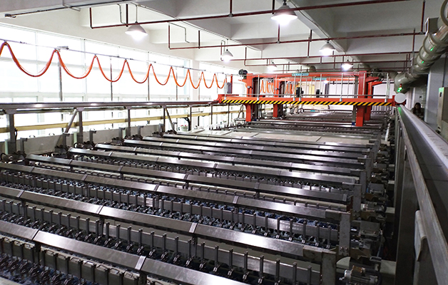
PCB Automatic Plating Line

PCB PTH Line

PCB LDI

PCB CCD Exposure Machine
Factory Show

PCB Manufacturing Base

Admin Receptionist

Meeting Room