
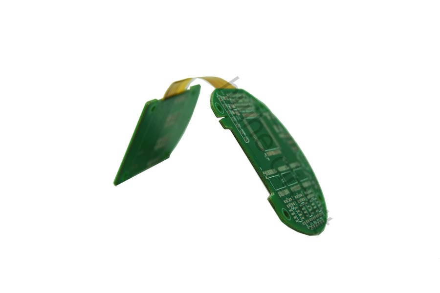
4 Layer ENIG SF302+FR4 Rigid-Flex PCB

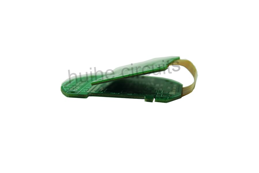
Points For Attention In The Design Of Rigid Flexible Combination Zone
1.The line should transition smoothly, and the direction of the line should be perpendicular to the bending direction.
2.The conductor shall be evenly distributed throughout the bending zone.
3.The width of the conductor shall be maximized throughout the bending zone.
4.PTH design should not be used in rigid flexible transition zone.
5.Bending radius of bending zone of rigid flexible PCB
Material Of Flexible PCB
Everyone is familiar with Rigid materials, and FR4 types of materials are often used. However, many requirements need to be taken into account for the rigid flexible PCB materials. Need to be suitable for adhesion, good heat resistance, in order to ensure that the rigid flexural bonding part of the same degree of expansion after heating without deformation. General manufacturers use resin series of rigid PCB materials.
For flexible materials, choose a substrate and cover film with smaller size expansion and contraction. Generally use the hard PI manufacturing materials, but also direct use of non-adhesive substrate for production. The flex materials are as follows:
Base Material: FCCL(Flexible Copper Clad Laminate)
Covering Membrane
Non-flow/Low Flow glue semi-cured sheet (Low Flow PP). Rigid and Flex connections are used for Rigid flex PCB, usually very thin PP.


